| MICROSCOPY | |||||||||||||||||||||||||||||||||||||||||||||||||||||||||||||||
Microscopy:Microscopy is any technique for producing visible images of structures or details too small to otherwise be seen by the human eye, using a microscope or other magnification tool. The microscope was first applied to biological material in the early seventeenth century by researchers such as Robert Hooke and Antoni van Leeuwenhoek, and remains a pivotal tool in learning about biology today.Microscopes:
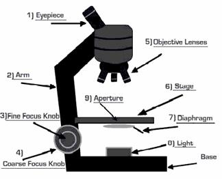
Optical microscope.The optical microscope is a type of microscope which uses visible light and a system of lenses to magnify images of small samples. Optical microscopes are the oldest and simplest of the microscopes.Basic Principles of Light Microscopy:
Basic Principles Electron Microscopy:
Comparison of the light and electron microscope:
A simple microscope is a microscope that uses only one lens for magnification, and is the original light microscope. Van Leeuwenhoek's microscopes consisted of a single, small, convex lens mounted on a plate with a mechanism to hold the material to be examined (the sample or specimen). A magnifying glass, an ordinary double convex lens having a short focal length, is a simple microscope. The reading lens and hand lens are instruments of this type. When an object is placed nearer such a lens than its principal focus, i.e., within its focal length, an image is produced that is erect and larger than the original object. The image is also virtual; i.e., it cannot be projected on a screen as can a real image.
How a microscope works:
In most microscopes, the eyepiece is a compound lens, which is made of two lenses one near the front and one near the back of the eyepiece tube forming an air separated couplet. In many designs, the virtual image comes to a focus between the two lenses of the eyepiece, the first lens bringing the real image to a focus and the second lens enabling the eye to focus on the now virtual image. In all microscopes the image is viewed with the eyes focused at infinity (mind that the position of the eye in the above figure is determined by the eye's focus). Headaches and tired eyes after using a microscope are usually signs that the eye is being forced to focus at a close distance rather than at infinity.
Compound microscope: The compound microscope uses many lenses in order to maximize magnification. The compound microscope consists essentially of two or more double convex lenses fixed in the two extremities of a hollow cylinder. The lower lens (nearest to the object) is called the objective; the upper lens (nearest to the eye of the observer), the eyepiece. The cylinder is mounted upright on a screw device, which permits it to be raised or lowered until the object is in focus, i.e., until a clear image is formed. When an object is in focus, a real, inverted image is formed by the lower lens at a point inside the principal focus of the upper lens. This image serves as an “object” for the upper lens which produces another image larger still (but virtual) and visible to the eye of the observer.
Comparison Microscope: A comparison microscope, sometimes known also as stereomicroscope or dissecting microscope, is a device used to analyze side-by-side specimens. It consists of two microscopes connected to an optical bridge, which results in a split view window. The comparison microscope is used in forensic sciences to compare microscopic patterns and identify or deny their common origin. The idea behind the comparison microscope is simple. Two microscopes are placed next to each other and the optical paths of each microscope are connected together by the optical bridge would help the forensic examiners to compare two specimens simultaneously instead of depending their memory.
The history of comparison microscope dated back to the 1920s where forensic ballistics was waiting for the inception. The controversial case of accused murderers and anarchists Nicola Sacco and Bartolomeo Vanzetti was such a beginning point. Comparison microscope was used for ballistic identification evidence in 1921 to help secure convictions of accused murderers Sacco and Vanzetti. In 1929, using a comparison microscope adapted for the purpose by Calvin Goddard and his partner Phillip Gravelle used similar techniques to absolve the Chicago Police Department of participation in the St. Valentine’s Day Massacre.
The Phase Contrast Microscope: The phase contrast microscope is widely used for examining such specimens as biological tissues. It is a type of light microscopy that enhances contrasts of transparent and colorless objects by influencing the optical path of light. The phase contrast microscope is able to show components in a cell or bacteria, which would be very difficult to see in an ordinary light microscope. Phase contrast is preferable to bright field microscopy when high magnifications (400x, 1000x) are needed and the specimen is colorless or the details so fine that color does not show up well.
Stereoscopic Microscope: A microscope having double eyepieces and objectives and independent light paths, producing a three-dimensional image. the stereoscopic type sees the object from two slightly different angles which provides the two images needed for the stereoscopic vision. The stereoscopic microscope gives a three-dimensional view of the object, while the same object appears flat when viewed through a compound microscope. Polarizing Microscope: The polarizing microscope is a much an optical measuring instrument as it is an instrument for the detailed examination of specimens. In addition to standard microscope optics, there is a polarizer in the condenser and another mounted in a slider in the tube above the objective, both in rotatable, graduated, mounts. The specimen is illuminated with plane polarized light, and its rotation of this light can be analyzed. The polarizing microscope is particularly useful in the study of birefringent materials such as crystals and strained non-crystalline substances. It is widely used for chemical microscopy and optical mineralogy.
Fluorescence Microscopy: A fluorescence microscope is much the same as a conventional light microscope with added features to enhance its capabilities. · The conventional microscope uses visible light (400-700 nanometers) to illuminate and produce a magnified image of a sample. · A fluorescence microscope, on the other hand, uses a much higher intensity light source which excites a fluorescent species in a sample of interest. This fluorescent species in turn emits a lower energy light of a longer wavelength that produces the magnified image instead of the original light source. These microscopes are often used for - Imaging structural components of small specimens, such as cells Conducting viability studies on cell populations (are they alive or dead?) Imaging the genetic material within a cell (DNA and RNA) Viewing specific cells within a larger population with techniques such as FISH
Working: In most cases the sample of interest is labeled with a fluorescent substance known as a fluorophore and then illuminated through the lens with the higher energy source. The illumination light is absorbed by the fluorophores (now attached to the sample) and causes them to emit a longer lower energy wavelength light. This fluorescent light can be separated from the surrounding radiation with filters designed for that specific wavelength allowing the viewer to see only that which is fluorescing.
The basic task of the fluorescence microscope is to let excitation light radiate the specimen and then sort out the much weaker emitted light from the image. First, the microscope has a filter that only lets through radiation with the specific wavelength that matches your fluorescing material. The radiation collides with the atoms in your specimen and electrons are excited to a higher energy level. When they relax to a lower level, they emit light. To become detectable (visible to the human eye) the fluorescence emitted from the sample is separated from the much brighter excitation light in a second filter. This works because the emitted light is of lower energy and has a longer wavelength than the light that is used for illumination.
Most of the fluorescence microscopes used in biology today are epi-fluorescence microscopes, meaning that both the excitation and the observation of the fluorescence occur above the sample. Most use a Xenon or Mercury arc-discharge lamp for the more intense light source.
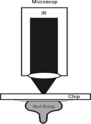
Infrared microscopy: A microscope that is equipped with infrared transmitting optics and that measures the infrared absorption of minute samples with the aid of photoelectric cells; images may be observed with image converters or television.
Principle: A IR lamp emits light between 800 and 2000 nm. The beam is focused on the bottom side of the semiconductor and the reflected signal is detected by an IR camera. In order to apply this method the back side of the electrical device has to be polished, otherwise the IR light would be scattered. Strengths: 1) Relatively cheap 2) Partially quantitative (strain fields) 3) Large and small areas can be investigated at medium resolution (ca. 1 µm). Weaknesses: 1) Well polished surfaces on both sides required 2) Involved specimen preparation if decoration is used 3) Often not very specific as to the nature of defects 4) Only applicable to "medium" defect densities 5) Not overly sensitive 6) Interpretation uncertain if decoration techniques are used.
Scanning electron microscope (SEM) : The scanning electron microscope (SEM) is a type of electron microscope capable of producing high-resolution images of a sample surface. Due to the manner in which the image is created, SEM images have a characteristic three-dimensional appearance and are useful for judging the surface structure of the sample. The SEM was pioneered by Manfred von Ardenne in the 1930s. The instrument was further developed by Charles Oatley and first commercialized by Cambridge Instruments
Scanning Process: In a typical SEM, electrons are thermionically emitted from a tungsten or lanthanum hexaboride (LaB6) cathode and are accelerated towards an anode; alternatively, electrons can be emitted via field emission (FE). Tungsten is used because it has the highest melting point and lowest vapour pressure of all metals, thereby allowing it to be heated for electron emission. The electron beam, which typically has an energy ranging from a few hundred eV to 100 keV, is focused by one or two condenser lenses into a beam with a very fine focal spot sized 0.4 nm to 5 nm. The beam passes through pairs of scanning coils or pairs of deflector plates in the electron optical column, typically in the objective lens, which deflect the beam horizontally and vertically so that it scans in a raster fashion over a rectangular area of the sample surface. When the primary electron beam interacts with the sample, the electrons lose energy by repeated scattering and absorption within a teardrop-shaped volume of the specimen known as the interaction volume, which extends from less than 100 nm to around 5 µm into the surface. The size of the interaction volume depends on the electrons' landing energy, the atomic number of the specimen and the specimen's density. The energy exchange between the electron beam and the sample results in the emission of electrons and electromagnetic radiation, which can be detected to produce an image
Transmission Electron Microscope (TEM): Transmission electron microscopy (TEM) is an imaging technique whereby a beam of electrons is transmitted through a specimen, then an image is formed, magnified and directed to appear either on a fluorescent screen or layer of photographic film (see electron microscope), or to be detected by a sensor such as a CCD camera. The first practical transmission electron microscope was built by Albert Prebus and James Hillier at the University of Toronto in 1938 using concepts developed earlier by Max Knoll and Ernst Ruska.
Working: TEMs work by using a tungsten filament to produce an electron beam in a vacuum chamber. The emitted electrons are accelerated through an electromagnetic field that also narrowly focuses the beam. The beam is then passed through the sample material. The specially prepared sample is a very thin (less than 100nm) slice of material. The electrons that pass through the sample hit a phosphor screen, CCD or film and produce an image. Where the sample has less density, more electrons get through and the image is brighter. A darker image is produced in areas where the sample is more dense and therefore less electrons pass through.
Using microscope / Steps:
First, think about what you want to do with the microscope. What is the maximum magnification you will need? Are you looking at a stained specimen? How much contrast/resolution do you require? Next, start setting up for viewing.
Mount the specimen on the stage: The cover slip must be up if there is one. High magnification objective lenses can't focus through a thick glass slide; they must be brought close to the specimen, which is why coverslips are so thin. The stage may be equipped with simple clips (less expensive microscopes), or with some type of slide holder. The slide may require manual positioning, or there may be a mechanical stage (preferred) that allows precise positioning without touching the slide.
Optimize the lighting: A light source should have a wide dynamic range, to provide high intensity illumination at high magnifications, and lower intensities so that the user can view comfortably at low magnifications. Better microscopes have a built-in illuminator, and the best microscopes have controls over light intensity and shape of the light beam. If your microscope requires an external light source, make sure that the light is aimed toward the middle of the condenser. Adjust illumination so that the field is bright without hurting the eyes.
Adjust the condenser: To adjust and align the microscope, start by reading the manual. If no manual is available, try using these guidelines. If the condenser is focusable, position it with the lens as close to the opening in the stage as you can get it. If the condenser has selectable options, set it to bright field. Start with the aperture diaphragm stopped down (high contrast). You should see the light that comes up through the specimen change brightness as you move the aperture diaphragm lever.
Think about what you are looking for: It is a lot harder to find something when you have no expectations as to its apprearance. How big is it? Will it be moving? Is it pigmented or stained, and if so what is its color? Where do you expect to find it on a slide? For example, students typically have a lot of trouble finding stained bacteria because with the unaided eye and at low magnifications the stuff looks like dirt. It helps to know that as smears dry down they usually leave rings so that the edge of a smear usually has the densest concentration of cells.
Focus, locate, and center the specimen: Start with the lowest magnification objective lens, to home in on the specimen and/or the part of the specimen you wish to examine. It is rather easy to find and focus on sections of tissues, especially if they are fixed and stained, as with most prepared slides. However it can be very difficult to locate living, minute specimens such as bacteria or unpigmented protists. A suspension of yeast cells makes a good practice specimen for finding difficult objects. -Use dark field mode (if available) to find unstained specimens. If not, start with high contrast (aperture diaphragm closed down). -Start with the specimen out of focus so that the stage and objective must be brought closer together. The first surface to come into focus as you bring stage and objective together is the top of the cover slip. With smears, a cover slip is frequently not used, so the first thing you see is the smear itself. -If you are having trouble, focus on the edge of the cover slip or an air bubble, or something that you can readily recognize. The top edge of the cover slip comes into focus first, then the bottom, which should be in the same plane as your specimen. -Once you have found the specimen, adjust contrast and intensity of illumination, and move the slide around until you have a good area for viewing.
Adjust eyepiece separation, focus: With a single ocular, there is nothing to do with the eyepiece except to keep it clean. With a binocular microscope (preferred) you need to adjust the eyepiece separation just like you do a pair of binoculars. Binocular vision is much more sensitive to light and detail than monocular vision, so if you have a binocular microscope, take advantage of it. One or both of the eyepieces may be a telescoping eyepiece, that is, you can focus it. Since very few people have eyes that are perfectly matched, most of us need to focus one eyepiece to match the other image. Look with the appropriate eye into the fixed eyepiece and focus with the microscope focus knob. Next, look into the adjustable eyepiece (with the other eye of course), and adjust the eyepiece, not the microscope.
Select an objective lens for viewing: The lowest power lens is usually 3.5 or 4x, and is used primarily for initially finding specimens. We sometimes call it the scanning lens for that reason. The most frequently used objective lens is the 10x lens, which gives a final magnification of 100x with a 10x ocular lens. For very small protists and for details in prepared slides such as cell organelles or mitotic figures, you will need a higher magnification. Typical high magnification lenses are 40x and 97x or 100x. The latter two magnifications are used exclusively with oil in order to improve resolution.
Magnification and Resolution:Magnification is how much bigger a sample appears to be under the microscope than it is in real life. Overall magnification = Objective lens x Eyepiece lens Resolution is the ability to distinguish between two points on an image.
Cases Solved: (Case Study) 1) Case of Thallium poisoning that was solved with electron microscopy. "The poisonous salt was expertly introduced into a soft drink bottle which was recapped," Dr. Rao explains, "Visual examination did not reveal any marks of tampering on the bottle or the cap. Micrographs obtained with a scanning electron microscope, however, clearly showed microscopic tell tale marks. Based on these, the defendant was convicted."
2) In yet another case, a murder victim was dragged along a carpet. In the process, some carpet fibres became lodged on the victim's body and clothing. Electron microscopy helped establish the unique identity of the carpet fibres and matched them to the scene of crime. Further analysis of the fibres with infrared spectrometry and thin-layer chromatography greatly increased the chances of conviction. Similarly, microscopic diatoms found in a murder victim's lungs and shoes were traced to a particular lake in Switzerland, helping the police to nab a peadophile serial killer thanks to electron microscopy.
3) Case Reading: Sacco and Vanzetti Case Forensic innovator Calvin Goddard offered ballistic identification evidence in 1921 to help secure convictions of accused murderers and anarchists Nicola Sacco and Bartolomeo Vanzetti. On April 8, 1927, Sacco and Vanzetti were finally sentenced to death in the electric chair. A worldwide outcry arose and Governor Alvin T. Fuller finally agreed to postpone the executions and set up a committee to reconsider the case. By this time, firearms examination had improved considerably, and it was now known that an automatic pistol could be traced by several different methods if both bullet and casing were recovered from the scene. Automatic pistols could now be traced by unique markings of the rifling on the bullet, by firing pin indentations on the fired primer, or by unique ejector and extractor marks on the casing. The committee appointed to review the case used the services of Calvin Goddard in 1927. Goddard used Philip Gravelle's newly-invented comparison microscope and helixometer, a hollow, lighted magnifier probe used to inspect gun barrels, to make an examination of Sacco’s .32 Colt, the bullet that killed Berardelli, and the spent casings recovered from the scene of the crime. In the presence of one of the defense experts, he fired a bullet from Sacco's gun into a wad of cotton and then put the ejected casing on the comparison microscope next to casings found at the scene. Then he looked at them carefully. The first two casings from the robbery did not match Sacco’s gun, but the third one did. Even the defense expert agreed that the two cartridges had been fired from the same gun. The second original defense expert also concurred. The committee upheld the convictions. In October 1961, ballistics tests were run with improved technology using Sacco's Colt automatic. The results confirmed that the bullet that killed the victim, Berardelli in 1920 came from the same .32 Colt Auto taken from the pistol in Sacco's possession. Subsequent investigations in 1983 also supported Goddard's findings.
REFERENCES:
www.infoplease.com www.microscopyu.com www.microscope-microscope.org www.nobelprize.org www.answers.com www.funsci.com Mr. B. K. Sharma, Class Notes (Amity University) B. Herman. Fluorescence Microscopy, 2nd ed., BIOS Scientific, UK, 1998. |
|||||||||||||||||||||||||||||||||||||||||||||||||||||||||||||||
| © 2008 : SANTOSH RAUT. www.santoshraut.com Delight Data System & Server |